
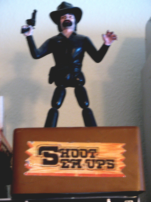
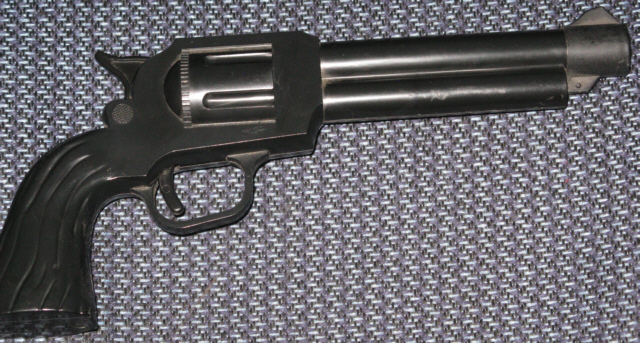
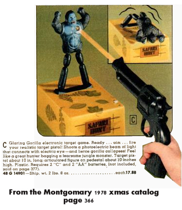
These are what the actual target and gun look like
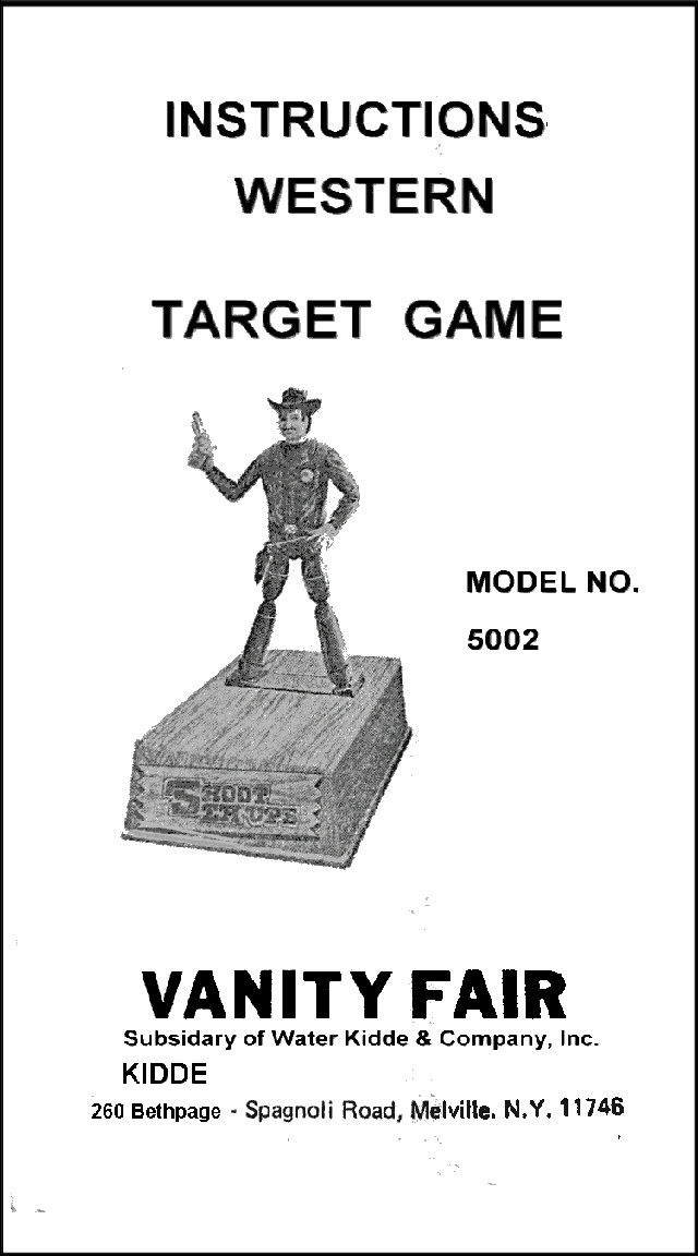
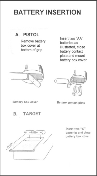
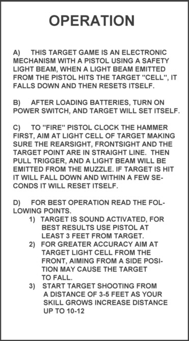
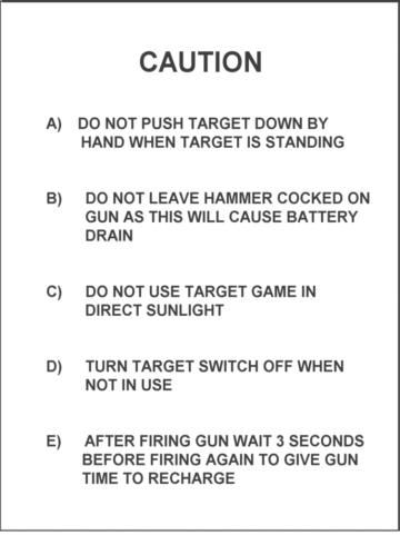
These pages are from the instruction booklet
THIS
IS
AN INTERESTING PRODUCT ORIGINALLY FROM THE MINDS AT NINTENDO.
LATER VANITY FAIR STARTED PRODUCING THIS ITEM WITH SOME SLIGHT VARIATIONS, BUT BASICALLY THE SAME THING.
LATER VANITY FAIR STARTED PRODUCING THIS ITEM WITH SOME SLIGHT VARIATIONS, BUT BASICALLY THE SAME THING.
These are products from Nintendo

Here is a comparison of Shoot Em Ups "Western" and Nintendo's "Custom Gunman"
(courtesy http://blog.beforemario.com )
So why the interest in what seems to be a simple toy, it's not as simple as it looks.
Below, is the original U.S. Patent granted

Click on this for the complete Patent
The above patent only covers 1/2 of the invention.
The
pistol is not shown in the patent application however there are some
other patents referenced'
The pistol is actually a flash gun, similar to a camera flash.
It uses a Xenon flash tube to illuminate the target it's aimed at.
The gun operates on 2 "AA" batteries, which are the source for the over 300 volts the gun generates to "fire" the Xenon tube.
Pulling the hammer back activates the guns circuitry. (so never leave the hammer pulled back when not in use as it will kill the batteries)
Within a few seconds a 47uf capacitor is charged to the over 300 volts needed to fire the tube.
Pulling the trigger completes the effect when the hammer comes to rest with a bright flash of white light.
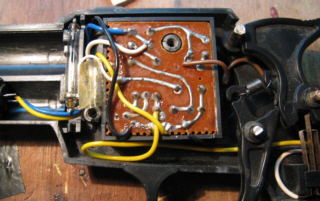
Tech Tips: During normal powerup of the gun it will draw about 20 ma.
This will drop to between 10-15ma. once the main cap is fully charged.
If you open the gun to work on it, and it has been on (hammer pulled back) keep your fingers away from the 47uf cap
In the photo above the flash tube is located just left of the board. Obviously it's glass so be careful handling it.
Notice also there are a fair about of wires connecting the switch, externally attached cap (in the barrel), and flash tube.
The flash tube if operating correctly will have over 300 volts on both ends of the tube, this is normal.
It's the third wire (ring around tube) that fires it.
The sight ring at the barrel end contains a lens, the assumption to increase the gun's range.
If you have any questions send me a message, link at the bottom
TARGET ASSEMBLY
This is where some of the genius takes place
The explanation of it's operation is explained in the patent shown above.
A simplification of it's operation is that using 2 steel cables which are attached to the segmented legs of the character, and a gear box transmission allows the character to stand or fall. Those 2 cables are also used to connect the output of the photocell to the control board'
This is done by a robust gearbox that tightens or loosens the legs to cause the character to rise or fall.
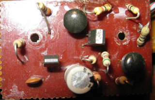
The mechanism is operated by a control board in the base. Components shown below.
Major Electronic Parts on Control Board
2 - 2SC461 transistor (smaller transistors) - NPN TO92 Ic 100ma
2 - Km 904F transistor - NPN TO92A Ic 500ma
1 - 100uf cap at 10v
1 - Photo Cell
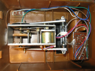
On the gearbox to the right, the arms on both sides are what the cables are connected to, they are insulted from it's chassis
This because the photcell signal rides on those cables. Those cables are electrically connected to the control board.
There is also a contact point to allow the control board to know when the arms have reached the rest position after motor starts running.
Tech tip:
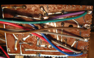
The wire connections are marked on the control board, but be careful handling the board as it's easy to pull one off.
One of the battery box wires is very short. The transistor basing is also shown on the board.
While repairing the #5002 Western, on Ebay I saw another model Vanity Shoot Em Ups target for sale.. I decided to buy it, though it's missing the gun and the target was said to be not working. What I find, will be posted up here. It's model is said to be #2004. Does that mean there is at least another version? or more?
Please email me if you know more about these.
The pistol is actually a flash gun, similar to a camera flash.
It uses a Xenon flash tube to illuminate the target it's aimed at.
The gun operates on 2 "AA" batteries, which are the source for the over 300 volts the gun generates to "fire" the Xenon tube.
Pulling the hammer back activates the guns circuitry. (so never leave the hammer pulled back when not in use as it will kill the batteries)
Within a few seconds a 47uf capacitor is charged to the over 300 volts needed to fire the tube.
Pulling the trigger completes the effect when the hammer comes to rest with a bright flash of white light.
Gun &
Target Information
GUN
Major Components
Charging Capacitor- 4.7uf at 350 volts
Xenon Flash Tube
Leaf Switch
Barrel Lens
Major Electronic Parts on Control Board
Transistor # CL 066 TO92A EBC 1amp
Choke #?
Transformer #?
Diode 1A
Firing Cap. 1 uf at 50v
Poly Cap. 032K
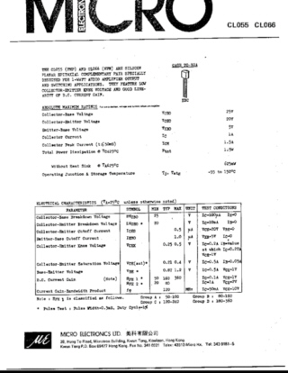
Below is the spec. sheet for the CL066
Tech Tip: I replaced the CL066e with a 2SC945, though the basing is different
A better substitute would have the same basing.


Tech Tips: During normal powerup of the gun it will draw about 20 ma.
This will drop to between 10-15ma. once the main cap is fully charged.
If you open the gun to work on it, and it has been on (hammer pulled back) keep your fingers away from the 47uf cap
In the photo above the flash tube is located just left of the board. Obviously it's glass so be careful handling it.
Notice also there are a fair about of wires connecting the switch, externally attached cap (in the barrel), and flash tube.
The flash tube if operating correctly will have over 300 volts on both ends of the tube, this is normal.
It's the third wire (ring around tube) that fires it.
The sight ring at the barrel end contains a lens, the assumption to increase the gun's range.
If you have any questions send me a message, link at the bottom
TARGET ASSEMBLY
This is where some of the genius takes place
The explanation of it's operation is explained in the patent shown above.
A simplification of it's operation is that using 2 steel cables which are attached to the segmented legs of the character, and a gear box transmission allows the character to stand or fall. Those 2 cables are also used to connect the output of the photocell to the control board'
This is done by a robust gearbox that tightens or loosens the legs to cause the character to rise or fall.
The mechanism is operated by a control board in the base. Components shown below.
Major Electronic Parts on Control Board
2 - 2SC461 transistor (smaller transistors) - NPN TO92 Ic 100ma
2 - Km 904F transistor - NPN TO92A Ic 500ma
1 - 100uf cap at 10v
1 - Photo Cell


On the gearbox to the right, the arms on both sides are what the cables are connected to, they are insulted from it's chassis
This because the photcell signal rides on those cables. Those cables are electrically connected to the control board.
There is also a contact point to allow the control board to know when the arms have reached the rest position after motor starts running.
Tech tip:
The wire connections are marked on the control board, but be careful handling the board as it's easy to pull one off.
One of the battery box wires is very short. The transistor basing is also shown on the board.
While repairing the #5002 Western, on Ebay I saw another model Vanity Shoot Em Ups target for sale.. I decided to buy it, though it's missing the gun and the target was said to be not working. What I find, will be posted up here. It's model is said to be #2004. Does that mean there is at least another version? or more?
Please email me if you know more about these.

SAFARI HUNT

The Safari Hunt Made it here from Canada.

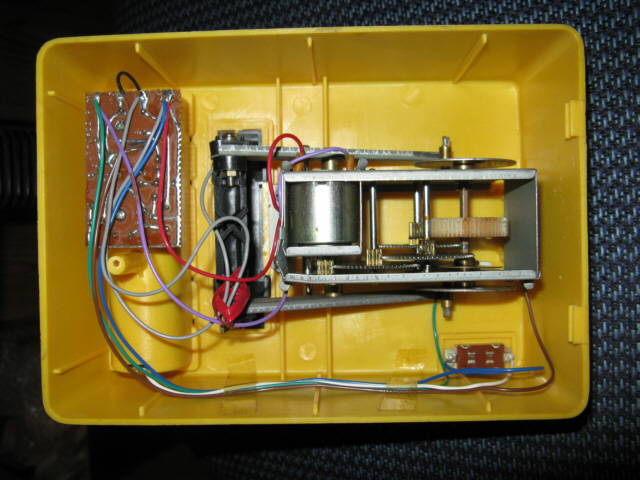
So...what did I find.
The previous owner was correct it wasn't operating correctly.
It struggled to complete a cycle, sometimes stopping completely before it should.
For some reason a previous owner removed the chassis screws, then returned only one screw, a incorrect size screw.
There are good reasons why the chassis needs to be secured properly. First there is a lot of torque applied to the steel cables to raise the character
and it needs to be straight.The second over looked by a previous owner, there is a wire attached to the chassis by one mounted screw.
That wire, provides the second half of the switch that the control board uses to determine the at rest start and stop position.
The one screw put back to secure the chassis was where the switch return wire is located and was too long to ground the wire.
The holes in the mounting posts are shallow, The screws used are very short, with a narrow diameter
Forcing longer and larger screws into the posts could cause them to break the posts or have them go through the cabinet top.
Note: the art on the cabinet is all individual labels
A quick mention about dealing with screws used with plastic posts. A common mistake is to press down hard on a screw when trying to remove them from plastic.
Never do this, the post can be stripped out of the material inside it, or worse cracked or worse yet snapped off.
Use the correct size screwdriver and use just enough force to keep the screwdriver tip in contact with the screw.
Last, never put larger screws in posts, everything mentioned above can and probably will happen.
I can't tell you how many cracked, split, or broken posts I've seen on products of all types.
These posts get more fragile as they age as well.
Now mounted correctly, wiring attached, fully tested and operating the way it's suppose to.
Wanted: A original manual or a scan of one

The Safari Hunt Made it here from Canada.


(Check out that face)
The mechanism in the base is identical to the Western Version.So...what did I find.
The previous owner was correct it wasn't operating correctly.
It struggled to complete a cycle, sometimes stopping completely before it should.
For some reason a previous owner removed the chassis screws, then returned only one screw, a incorrect size screw.
There are good reasons why the chassis needs to be secured properly. First there is a lot of torque applied to the steel cables to raise the character
and it needs to be straight.The second over looked by a previous owner, there is a wire attached to the chassis by one mounted screw.
That wire, provides the second half of the switch that the control board uses to determine the at rest start and stop position.
The one screw put back to secure the chassis was where the switch return wire is located and was too long to ground the wire.
The holes in the mounting posts are shallow, The screws used are very short, with a narrow diameter
Forcing longer and larger screws into the posts could cause them to break the posts or have them go through the cabinet top.
Note: the art on the cabinet is all individual labels
A few Tech Tips:
Do not misplace the mechanism chassis screws or the control
board screws if removed as they are almost impossible to replace. the
size and
length is critical.A quick mention about dealing with screws used with plastic posts. A common mistake is to press down hard on a screw when trying to remove them from plastic.
Never do this, the post can be stripped out of the material inside it, or worse cracked or worse yet snapped off.
Use the correct size screwdriver and use just enough force to keep the screwdriver tip in contact with the screw.
Last, never put larger screws in posts, everything mentioned above can and probably will happen.
I can't tell you how many cracked, split, or broken posts I've seen on products of all types.
These posts get more fragile as they age as well.
Now mounted correctly, wiring attached, fully tested and operating the way it's suppose to.
Wanted: A original manual or a scan of one
If you have
information about these Vanity
Fair products or (Kidee) on Long Island or have questions
Contact me here